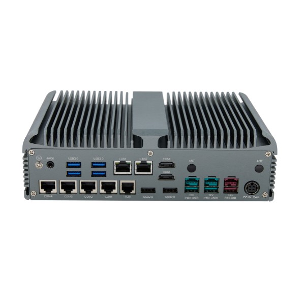
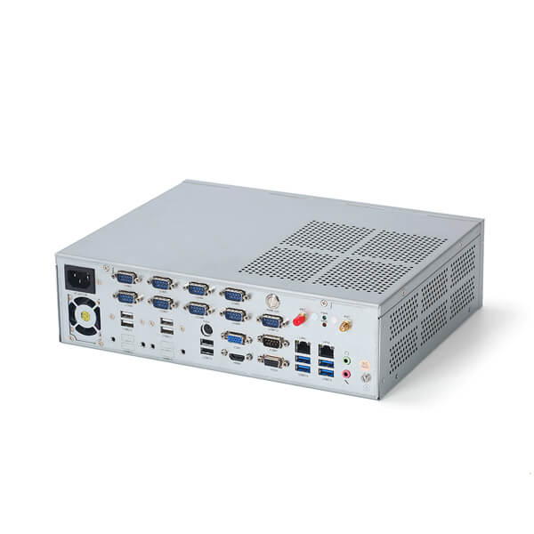
Industrial computer interfaces connect PCs with controllers, sensors, cameras, displays, and other equipment. RS232 is commonly used for point-to-point serial connections; RS485 supports differential serial communication and bus arrangements. Ethernet, USB, CAN, and digital I/O serve different integration needs. Selecting them requires more than matching connector shapes or counting ports.
For a reliable specification, identify the electrical interface, physical connector, application protocol, driver, and wiring requirements for every connected device. These layers determine whether equipment can exchange useful data rather than merely plug together.
Interfaces, Connectors, and Protocols Describe Different Layers
An interface describes how signals are exchanged. A connector provides the physical connection. A protocol defines how communicating devices structure and interpret messages. The operating system then exposes a device through a driver or logical channel.
For example, an RS485 interface might use a terminal block and carry Modbus RTU messages. Another device might use Ethernet with an RJ45 connector and communicate through Modbus TCP. The two devices need different hardware and software arrangements even though both use Modbus.
COM1 in Windows is a logical serial-port designation, not proof of RS232 signaling. Similarly, a DB9-style connector may carry RS232, RS422, RS485, or a manufacturer-specific pinout. Obtain the pin definition before connecting equipment.
Treat software support as part of the interface specification. A hardware port does not guarantee the application understands a device’s command set, supports its protocol, or has an appropriate driver for the chosen operating system.
RS232, RS422, and RS485 Support Different Serial Connections
RS232 for Point-to-Point Devices
RS232 uses single-ended signaling and is commonly found on legacy controllers, instruments, scanners, and service interfaces. It is suitable for a direct connection between two devices when cable characteristics, data rate, grounding, and noise conditions are appropriate.
Check transmit, receive, and signal-ground connections, plus any required handshake lines. DTE and DCE arrangements can require different cable wiring; a straight-through cable and a null-modem cable are not interchangeable in every installation.
Do not assume one universal cable-distance limit. Practical reach depends on the data rate, cable capacitance, transceivers, and environment. Use the equipment documentation and validate the actual connection rather than relying on a generic length figure.
RS485 for Differential Serial Networks
RS485 uses differential signaling and can support multiple devices on a shared bus. Common two-wire arrangements operate in half duplex, so transmission and reception occur at different times on the same signal pair. Four-wire arrangements use separate pairs for the two directions.
The protocol and system design must coordinate bus access. Connecting several devices does not make their messages compatible or prevent simultaneous transmissions automatically. For a polling application, identify device addresses, response times, and the computer’s direction-control method.
Cable topology also matters. A main trunk with short stubs is the conventional starting point; long branches can create reflections. Where transmission-line termination is required, termination should match the cable impedance and be placed appropriately at the ends rather than at every node.
Check biasing and receiver fail-safe behavior using the actual devices. Some ports include switchable termination or bias components; others require external provisions. Document these settings so replacement hardware does not silently change the bus.
RS422 for Differential Links With Separate Signal Pairs
RS422 is another differential serial interface, commonly used where separate transmit and receive pairs suit the equipment. Its transmitter and receiver arrangements differ from a multipoint RS485 system.
A configurable serial port may offer RS232, RS422, and RS485 modes, but configuration can involve firmware, software, jumpers, or switches. Confirm the required mode and pinout before commissioning. Never connect board-level TTL serial directly to an RS232 port; their electrical levels differ.
Compare Common Industrial Computer Interfaces
| Interface | Typical connection role | Main compatibility check |
|---|---|---|
| RS232 | Individual instruments and legacy equipment | Pinout, handshake, serial settings, and device commands |
| RS485 | Metering and serial device buses | Wiring mode, bus access, addressing, and termination |
| RS422 | Differential serial links | Pair assignment and transmitter/receiver arrangement |
| Ethernet | Controllers, cameras, servers, and gateways | Protocol, network controller, bandwidth, and software support |
| USB | Scanners, cameras, adapters, and service devices | Host capability, drivers, throughput, and power budget |
| CAN | Machinery and vehicle-related networks | Controller, transceiver, bitrate, and higher-level protocol |
| Digital I/O | Discrete status and command signals | Voltage, polarity, current, isolation, and switching type |
| HDMI or DisplayPort | Operator displays | Display mode, cable retention, and supported output configuration |
Use the table to organize requirements, not to prescribe a standard port set. One application may need a single network connection; another may require several independent serial channels and expansion cards.
Ethernet and USB Require More Than Nominal Bandwidth
Ethernet connects industrial PCs to controllers, network cameras, supervisory systems, and business networks. Multiple ports can provide separate physical connections, but separation depends on network configuration. Two sockets do not automatically create a secure boundary or redundant communication.
Confirm the application protocol. EtherCAT, PROFINET, EtherNet/IP, and ordinary TCP/IP applications can have different controller, runtime, timing, and qualification requirements. An Ethernet socket alone does not establish support for every industrial Ethernet system.
For camera applications, evaluate aggregate traffic, packet handling, acquisition software, and the network architecture. A nominal link speed is not the same as available application throughput. PoE support must also be explicit: a port does not supply power merely because it uses Ethernet.
USB supports many useful peripherals, but devices can share controllers and bandwidth internally. Several high-data-rate cameras or storage devices may compete even when they occupy separate connectors. Examine controller topology and test simultaneous operation.
USB-C describes the connector format, not a promise of every function associated with it. Check data capability, display modes, and power roles independently. For deployment, also consider retention, cable routing, hub quality, and recognition after restart or reconnect.
CAN and Digital I/O Need Explicit Electrical Specifications
CAN integration requires suitable controller and transceiver hardware together with software access. Higher-level protocols such as CANopen and SAE J1939 add message interpretation and application behavior; they are not automatically supplied by a CAN connector.
Specify whether the network uses Classical CAN or CAN FD, along with required bitrate, protocol, and device support. Check bus termination, cable arrangement, and driver/API compatibility with the application. An adapter that can receive frames is not necessarily a complete protocol solution.
Digital I/O handles discrete states such as a sensor indication or an enable command. Confirm input voltage ranges, output type, current capability, polarity, and whether signals are isolated. A logic-level GPIO cannot be assumed compatible with an industrial field signal.
Distinguish dry-contact sensing, transistor outputs, and relay outputs. They involve different wiring and electrical limits. Digital I/O is also separate from analog acquisition: measuring a variable signal may require a suitable input module or data-acquisition device. Safety functions require the approved safety architecture rather than ordinary PC I/O.
Specify Isolation, Cabling, and Recovery as Part of Integration
Electrical isolation can help separate grounds and manage disturbances, but its scope and rating must be understood. Ask which circuits are isolated and whether isolated power is included. ESD protection, surge protection, and isolation describe different capabilities.
Follow device-specific grounding, shielding, and wiring instructions. Differential signaling improves noise rejection but does not make a network immune to unlimited common-mode voltage or poor installation. Cable routing, bonding, and protective components influence the complete result.
Serial-to-Ethernet device servers can extend access to existing equipment, but distinguish data transport from protocol conversion. A transparent server may carry serial bytes across a network without translating their meaning. If conversion between Modbus RTU and Modbus TCP is required, specify that gateway function explicitly.
Include failure recovery in acceptance. Verify how the application behaves after a cable disconnect, device reboot, or network interruption. Document stable port identification, serial settings, drivers, and adapter models. A connection that works once on a bench may still fail after unattended restart.
Conclusion
Industrial computer interfaces should be specified as complete connections: electrical standard, connector, protocol, software, wiring, and recovery behavior. Build this schedule before selecting the computer. It exposes compatibility gaps early and provides a clearer basis for commissioning than a list of RS232, RS485, USB, and Ethernet ports.