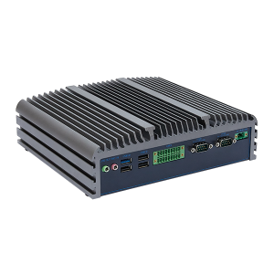
Industrial computer operating temperature is the ambient temperature range in which an industrial computer functions reliably while powered on. Storage temperature, in contrast, applies when the unit is off and stored; it is typically wider because the system generates no internal heat. For a concrete example, industrial PCs often have an operating temperature of 0°C to 50°C but a storage temperature of -20°C to 70°C.
Recognizing this distinction helps you interpret specifications accurately, choose the right temperature range for your applications, and avoid common pitfalls. Selecting an incorrect range may lead to unexpected shutdowns, data corruption, or hardware damage. Such failures can be costly in terms of both repair and downtime. Therefore, understanding temperature ratings is critical for selecting the appropriate hardware.
Operating vs. Storage Temperatures: What’s the Difference?
Definition of Operating Temperature
The industrial computer operating temperature defines the ambient conditions in which a system can run while powered on. This rating covers the full duration of active operation. The system must boot, process data, and communicate with other devices within this specified window. Manufacturers determine this value through rigorous testing. They subject the unit to extreme conditions in controlled chambers. The resulting figure represents the ambient air temperature surrounding the device, not the internal component temperature.
This distinction matters because internal heat generation adds to the ambient load. A system rated for a specific operating temperature can handle that external level while managing its own thermal output. The rating assumes the unit operates continuously at that ambient level without performance degradation. Any deviation above the upper limit risks instability. Any drop below the lower limit may prevent startup entirely.
Key Differences from Storage
Storage temperature covers the conditions a unit can endure while powered off. This rating is almost always wider than the operational one. The reason is simple: an inactive system generates no internal heat. Components face less stress without electrical current flowing through them. A device might operate comfortably from 0°C to 50°C but survive storage from -20°C to 70°C. These two temperature bands serve different purposes.
The operational rating protects functionality during use. The storage rating protects physical integrity during transport or idle periods. Industrial PCs in cold warehouses may sit below their operational minimum for months. They suffer no damage as long as they remain within the storage range. Once powered on, however, the operational limits apply immediately. A unit stored at -20°C may need a warm-up period before it can boot safely. This transition period is critical for avoiding condensation and thermal shock.
The table below summarizes the core distinctions.
| Aspect | Operating Temperature | Storage Temperature |
|---|---|---|
| System state | Powered on | Powered off |
| Typical width | Narrower | Wider |
| Primary risk | Shutdown, data loss | Physical damage |
| Example range | 0°C to 50°C | -20°C to 70°C |
Understanding these differences prevents costly mistakes. Engineers who confuse the two may deploy a system in conditions it cannot handle. A unit rated only for storage at -20°C will not necessarily function at that level. The temperature range for active use demands more from every component. Capacitors, processors, and storage drives all behave differently under load. The operational rating accounts for these dynamics. The storage rating does not. Always verify both specifications before installation. The operational figure determines real-world viability. The storage figure only informs logistics and handling procedures.
What Operating Temperature Ranges Do Industrial PCs Support?
Standard and Wide-Temperature Ranges
Industrial computer operating temperature ratings fall into two main categories. The standard range covers 0°C to 60°C. This band suits most controlled indoor environments. The wide-temperature range extends from –40°C to 85°C. Systems built for this broader span can start up and run stably within their labeled ambient limits. These temperature bands reflect different design priorities. Standard units prioritize cost efficiency for moderate conditions. Wide-temperature industrial pcs add specialized components and thermal management to handle extremes.
The table below compares these two ranges.
| Range Type | Temperature Span | Typical Use Case |
|---|---|---|
| Standard | 0°C to 60°C | Indoor factory floors |
| Wide-temperature | –40°C to 85°C | Unheated outdoor kiosks |
A standard unit works well on a climate-controlled production floor. A wide-temperature model handles a roadside cabinet in winter. The operating temperature rating tells you which environment the system can survive.
Matching Ranges to Applications
Selecting the correct temperature range depends on your deployment conditions. Standard industrial pcs fit indoor factory floors where heating and cooling keep conditions moderate. These applications rarely see temperatures outside the 0°C to 60°C band. Wide-temperature systems serve unheated outdoor kiosks, remote monitoring stations, and cold storage facilities. These applications demand operation across the full –40°C to 85°C span.
Consider a traffic management cabinet in a northern climate. Winter temperatures may drop well below freezing. A standard unit would fail to boot. A wide-temperature model starts reliably at –40°C. Conversely, a standard unit in a temperature-controlled warehouse offers a cost-effective solution. Matching the temperature range to your actual environment prevents both under-specification and unnecessary expense. Review historical weather data and facility records before making a final choice.
How to Choose Temperature Ranges for Actual Installation Conditions
Accurately determining your operating temperature requirements prevents costly system failures. Many deployments fail because engineers estimate conditions instead of measuring them. The first step involves gathering real-world data from the target location.
Measuring Environmental Conditions
Begin by measuring the worst-case ambient temperature at your installation site. Summer afternoons when the sun is at its peak produce the highest thermal load. Place a data logger at the exact mounting location. Let it record temperature continuously for at least one full week. Review the maximum reading during the hottest part of the day. This figure represents your baseline ambient condition.
Do not rely on weather station data alone. Those readings come from shaded, ventilated enclosures far from your equipment. The temperature next to a metal wall or near a heat source can be significantly higher. Measure inside the cabinet or at the device mounting point. A thermocouple connected to a multimeter gives a direct reading. An infrared thermometer offers a quick spot check. Use multiple sensors if the location has uneven airflow or varying heat sources.
Record temperature at different times of day. Morning lows differ from midday peaks. Repeat measurements across different seasons. A location comfortable in spring may exceed limits in August. Historical climate data provides context but does not replace on-site measurement. Always validate assumptions with direct observation. A single reading on a mild day does not reveal the true extremes. Log data at intervals no longer than ten minutes to capture brief thermal spikes.
Consider secondary factors beyond air temperature. Direct sunlight heats the enclosure surface well above ambient. Nearby machinery radiates heat. Poor ventilation traps warm air. These factors raise the effective thermal load on the industrial computer operating temperature rating. Account for every heat source near the installation point.
Accounting for Enclosures and Airflow
Enclosures create a microclimate around the computer. A sealed metal box absorbs solar radiation. Internal components generate additional heat. The temperature inside an enclosure can be 10°C to 20°C higher than the external air. This difference is critical when selecting a temperature range for your system.
Measure temperature inside the enclosure during peak conditions. Place the sensor near the computer’s air intake. Record values for several days. This reading shows the actual environment the system faces. Do not rely on external ambient temperature ranges alone. The interior condition determines real-world performance. Position the system away from the top of the cabinet where hot air naturally collects.
Airflow affects heat dissipation significantly. A fan-cooled enclosure moves hot air away from components. A sealed fanless design relies on conduction through the chassis walls. Both approaches change how heat accumulates. Poor airflow causes hotspots. Even a small ventilation gap can reduce internal temperature by several degrees. Consider adding passive vents to improve circulation inside the cabinet.
Add a safety margin to your measured peak temperature. A margin of 5°C to 10°C accounts for measurement error and unusual weather events. A measured peak of 45°C inside the enclosure plus a 10°C margin requires a system rated for at least 55°C. This buffer ensures reliable operation during unexpected conditions.
Without this margin, a brief heat spike can push the system beyond its rated limit. The final selection process combines measured data, enclosure analysis, and safety margin. A standard range system works when the adjusted internal peak stays below 50°C. A wide-temperature model becomes necessary when the adjusted peak exceeds that threshold. Always verify your calculations against manufacturer specifications. Select the next higher standard rating when your calculated target falls between two published ranges.
What Happens When Industrial PCs Run Too Hot or Too Cold?
System Shutdown and Data Loss
Exceeding the rated operating temperature triggers a cascade of failures. The system may shut down without warning. This sudden loss of power interrupts active processes. Unsaved data disappears instantly. Files in transit may corrupt during the write cycle. A database update could leave records in an inconsistent state. These failures disrupt operations and require time to recover.
Heat also degrades wireless connectivity. WiFi modules operate within a narrow thermal window. Elevated temperatures cause signal dropouts and reduced range. The network link may fail entirely. Components face permanent damage beyond temporary glitches. Capacitors dry out. Solder joints crack. Semiconductor junctions degrade. These failures do not reverse when temperatures return to normal. A unit pushed past its operating temperature ratings may never recover full functionality.
Understanding Published Specs
Manufacturers test operating temperature ratings under stable, controlled conditions. A thermal chamber holds a constant ambient level for a set duration. The unit runs a standardized workload. This method produces repeatable results. Real deployments rarely match these ideal conditions. A brief heat spike can push internal temperatures past the tested limit. Direct sunlight on an enclosure creates a transient thermal load. A nearby motor cycles on and off. These events last minutes or hours. The published temperature range does not account for every real-world fluctuation.
Engineers must interpret specifications with this gap in mind. A rating of 0°C to 60°C assumes steady ambient air. It does not promise survival during a temporary 65°C surge. The system may throttle performance or shut down to protect itself. Repeated exposure to such transients shortens component life. Always compare published limits against measured worst-case conditions. Add margin for the unexpected. A system rated exactly to your peak ambient leaves no room for error. The operating temperature figure is a baseline, not a guarantee against every thermal event.
How Wide-Temperature Industrial PCs Handle Heat and Cold
Fanless Cooling and Thermal Design
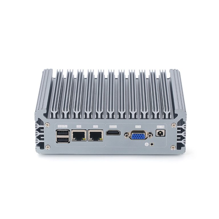
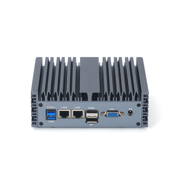
Fanless cooling forms the foundation for systems designed to handle extreme ambient conditions. This approach removes all moving parts from the thermal management system. Heat moves away from processors and power components through direct conduction. A large aluminum or copper heatsink attaches to each heat-generating element. Thermal interface materials fill microscopic gaps between the chip and the heatsink. The chassis itself often acts as a secondary heatsink. Heat spreads across the enclosure surface and dissipates into the surrounding air. This design eliminates fans that can fail or collect dust.
Fanless cooling enables reliable performance in environments with airborne particulates or vibration. A sealed enclosure prevents contaminants from entering the system. The absence of moving parts removes a common failure point. Thermal designers must carefully route heat paths through the chassis. Heat pipes may carry thermal energy from dense processor areas to cooler regions of the enclosure.
Every component placement considers airflow patterns, even without active fans. The system must maintain safe internal temperatures at both the upper and lower ends of the operating range. At extreme cold, the same conductive path helps components reach their minimum operating temperature quickly.
Component Selection Strategies
Component selection determines whether a system can achieve wide ratings. Standard commercial-grade parts operate reliably only within a narrow temperature range. Industrial systems built for extreme conditions use components rated from negative forty to positive eighty-five degrees Celsius. Processors, memory modules, storage drives, and power management ICs must all meet this specification. A single part rated for a narrower range becomes the weakest link. Manufacturers source components that maintain timing characteristics and electrical performance across the full span.
System-level thermal management coordinates component behavior under stress. Firmware may adjust clock speeds or fan curves based on internal temperature sensors. Power supply circuits include components with higher voltage tolerance at temperature extremes. Storage devices use industrial-grade NAND flash rated for extended-temperature operation.
The overall design validates that every component operates within its specification simultaneously. Testing confirms the system starts and runs stably across the entire rated operating band. This coordinated approach separates true wide-temperature systems from assemblies that merely use one or two ruggedized parts.
Conclusion
Industrial computer operating temperature differs from storage ratings. Typical ranges span 0°C–60°C to –40°C–85°C. Always measure your environment and add a safety margin. Exceeding limits causes shutdowns, data loss, and permanent damage. Wide-temperature industrial pcs rely on fanless cooling and industrial-grade components.
Evaluate your worst-case ambient plus enclosure heat rise. Pick a temperature range with at least 10°C margin. Consult a supplier if uncertain. These steps protect your industrial pcs across demanding applications. Use our temperature calculator or talk to an engineer to find the right operating temperature solution for your environment.